Giriş
Follow this guide to remove or replace the logic board on an iPad Pro 9.7".
This guide is written with a cellular model iPad Pro. If your iPad is not the cellular enabled model, skip the first step.
For your safety, discharge the battery below 25% before disassembling your device. This reduces the risk of a dangerous thermal event if the battery is accidentally damaged during the repair. If your battery is swollen, take appropriate precautions.
Some photos in this guide are from a different model and may contain slight visual discrepancies, but they won't affect the guide procedure.
Neye ihtiyacın var
-
-
Insert a SIM card eject tool, bit, or a paperclip into the small hole in the SIM card tray, located near the bottom edge of the iPad.
-
Press firmly to eject the tray.
-
Remove the SIM tray.
-
-
-
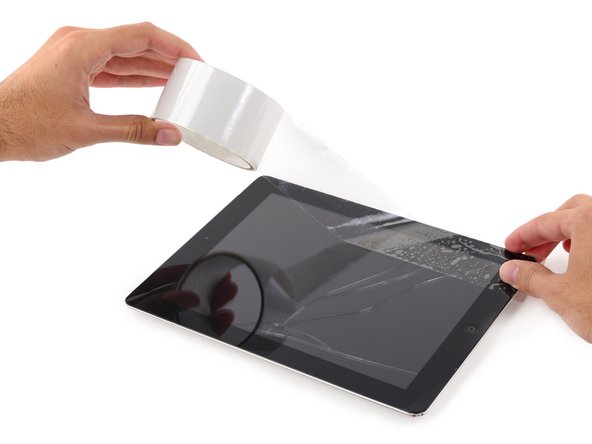
If your display glass is cracked, keep further breakage contained and prevent bodily harm during your repair by taping the glass.
-
Lay overlapping strips of clear packing tape over the iPad's display until the whole face is covered.
-
Do your best to follow the rest of the guide as described. However, once the glass is broken, it will likely continue to crack as you work, and you may need to use a metal prying tool to scoop the glass out.
-
-
-
Elevate the iPad enough for the Anti-Clamp's arms to rest above and below the screen.
-
Pull the blue handle towards the hinge to disengage opening mode.
-
Position the suction cups near the top edge of the iPad—one on the front, and one on the back.
-
Push down on the cups to apply suction to the desired area.
-
-
-
Push the blue handle away from the hinge to engage opening mode.
-
Turn the handle clockwise until you see the cups start to stretch.
-
Wait one minute to give the adhesive a chance to release and present an opening gap.
-
Insert an opening pick under the screen when the Anti-Clamp creates a large enough gap.
-
Skip the next two steps.
-
-
-
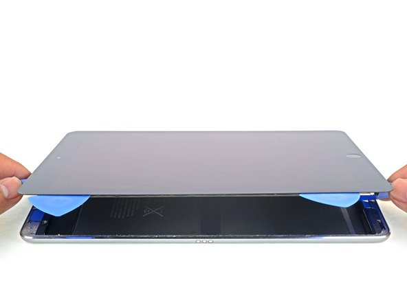
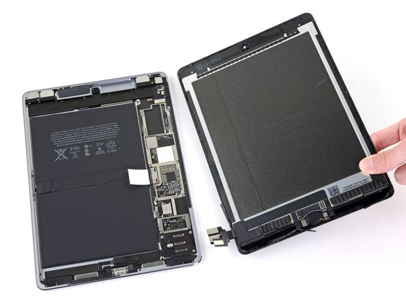
Use picks to ensure most of the adhesive has been cut through on the top, left, and bottom sides.
-
Twist the top and bottom picks to separate the display assembly from the rear case.
-
-
-
Use a Phillips screwdriver to remove the eleven 1.3 mm screws securing the EMI shield.
-
-
-
-
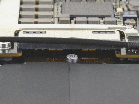
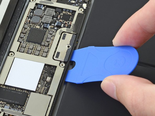
Slide the battery blocker underneath the left side of the logic board's battery connector at a 35 degree angle.
-
Leave the battery blocker in place as you work.
-
-
-
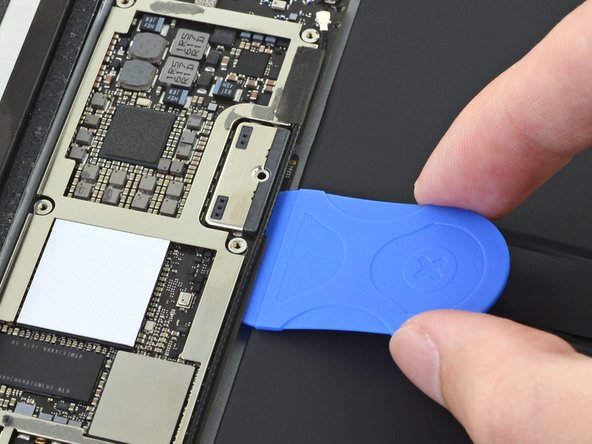
Apply a few drops of high-concentration (90% or higher) isopropyl alcohol under the logic board to the left and right of the battery connection.
-
Wait one minute for the isopropyl alcohol to weaken the adhesive under the logic board.
-
Try to insert the battery blocker. If the logic board doesn't easily lift up, apply a few more drops of isopropyl alcohol.
-
-
-
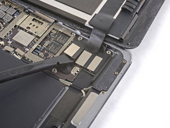
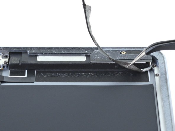
Use a Phillips screwdriver to remove the three 1.3 mm Phillips screws securing the display cable bracket.
-
-
-
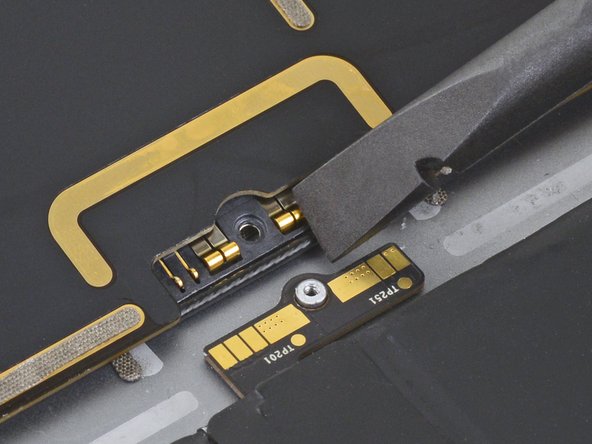
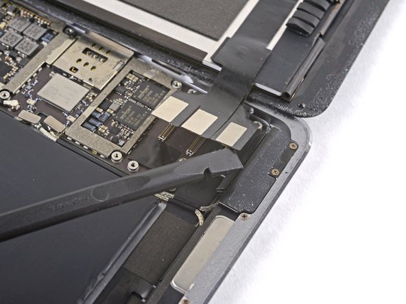
Use the flat end of the spudger to disconnect the display assembly connector from the motherboard socket.
-
-
-
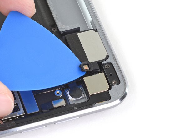
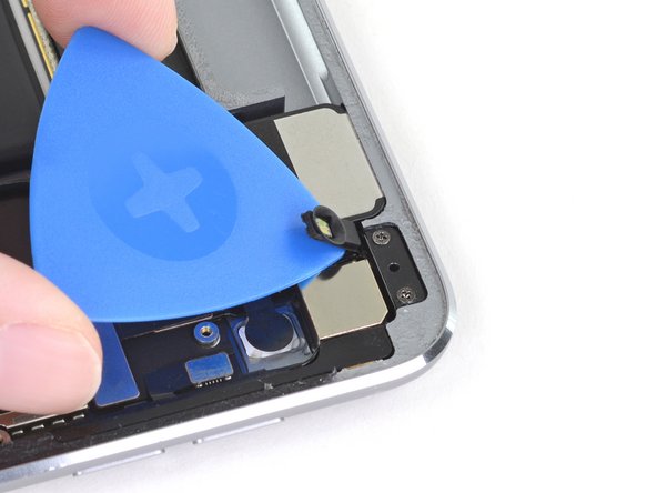
Slide an opening pick under the right ambient light sensor to loosen its adhesive.
-
-
-
Use a Phillips screwdriver to remove the four 1.9 mm-long screws securing the upper speaker to the frame.
-
-
-
Apply a few drops of high-concentration (90% or higher) isopropyl alcohol under the upper speaker.
-
Wait one minute for the isopropyl alcohol to weaken the adhesive under the upper speaker.
-
-
-
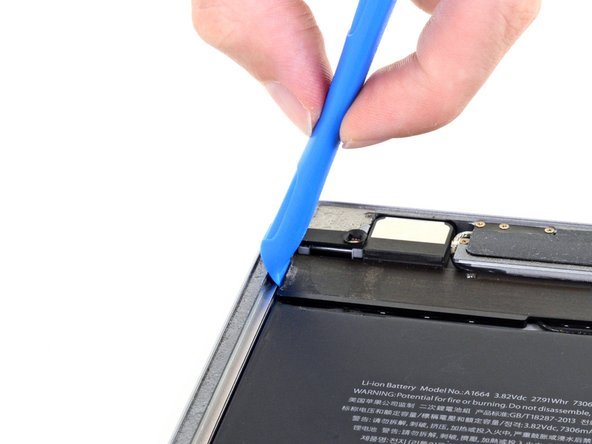
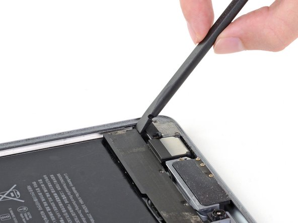
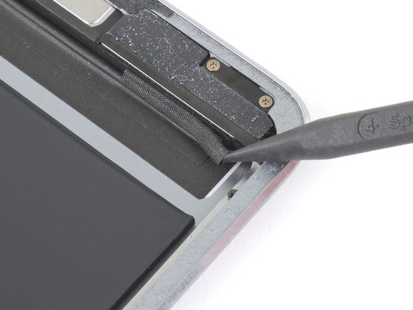
Use an opening tool to pry up the left edge of the upper speaker.
-
-
-
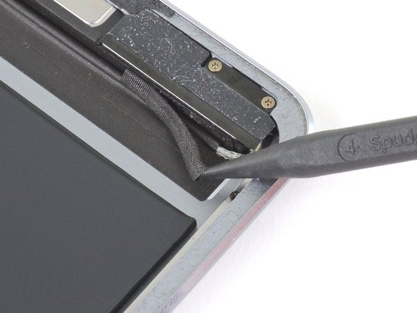
Use the flat end of a spudger to push the left side of the upper speaker toward the battery just enough for the left speaker to slide out of its recess in the frame.
-
-
-
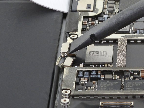
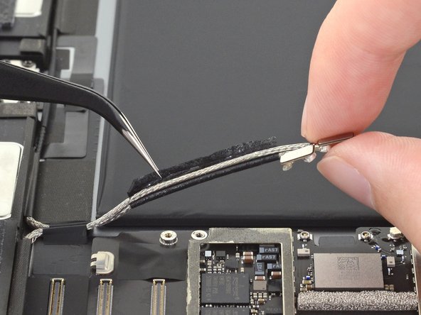
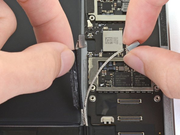
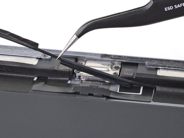
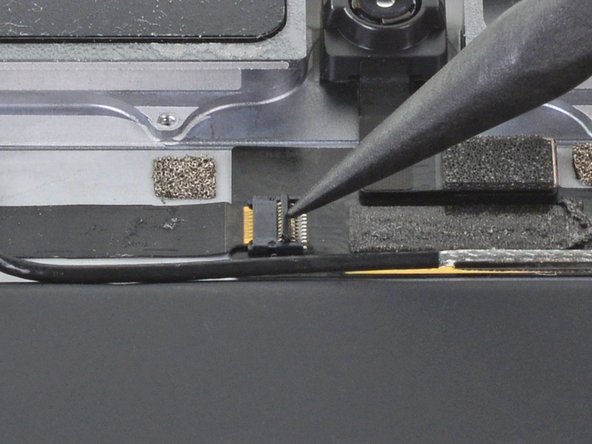
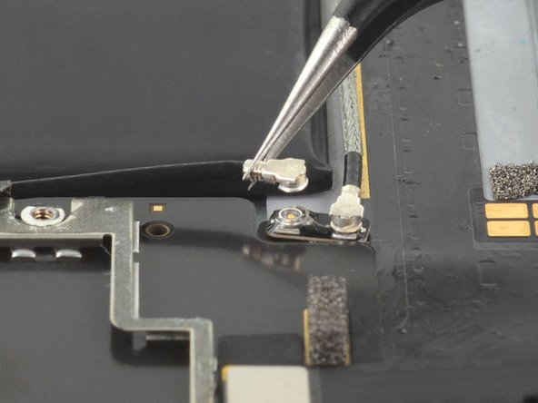
Use the flat end of a spudger to disconnect the right antenna's coaxial connector from its socket.
-
-
-
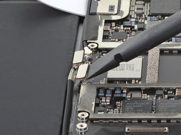
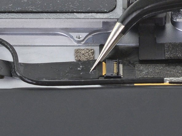
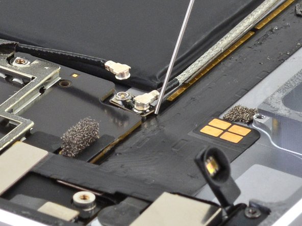
Use the flat end of a spudger to disconnect the left antenna's coaxial connector from its socket.
-
-
-
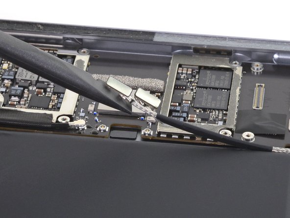
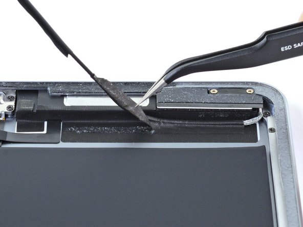
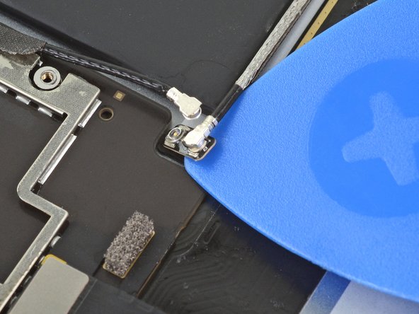
Use the flat end of a spudger to lift the bundled left and right antenna cables away from the frame.
-
-
-
Use a pair of tweezers to remove the adhesive that was securing the bundled antenna cables to the frame.
-
-
-
Use a pair of tweezers to peel up the sticker bundling the left and right antenna cables together.
-
-
-
Use a pair of tweezers to lift up the small sticker near the lower right speaker securing the right antenna to the frame.
-
-
-
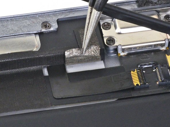
Use the pointed end of a spudger to detach the foam spacer adhered to the second right antenna sticker.
-
-
-
Remove the foam spacer from the second right antenna sticker.
-
-
-
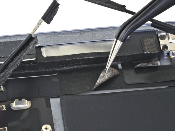
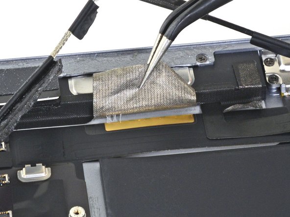
Use a pair of tweezers to detach the large right antenna sticker between the logic board and the antenna.
-
-
-
Use a pair of tweezers to lift up the small sticker next to the lower right speaker securing the left antenna cable to the frame.
-
-
-
Use a pair of tweezers to detach the large left antenna cable sticker near the lower right speaker.
-
-
-
Use a pair of tweezers to lift the left antenna and its third sticker away from the Lightning port area of the frame.
-
-
-
Use the pointed end of a spudger to detach the foam spacer adhered to the fourth left antenna cable sticker.
-
-
-
Remove the foam spacer from the fourth left antenna cable sticker.
-
-
-
Use a pair of tweezers to remove the sticker covering the left ambient light sensor's ZIF connector.
-
-
-
Use the pointed end of a spudger to flip up the locking flap on the left ambient light sensor's ZIF connector.
-
-
-
Use a pair of tweezers to grip the left ambient light sensor ribbon cable as close as possible to its contacts.
-
Pull the ribbon cable out of the ZIF connector.
-
-
-
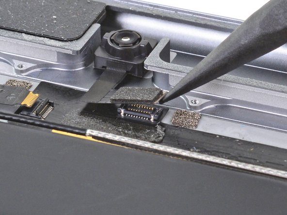
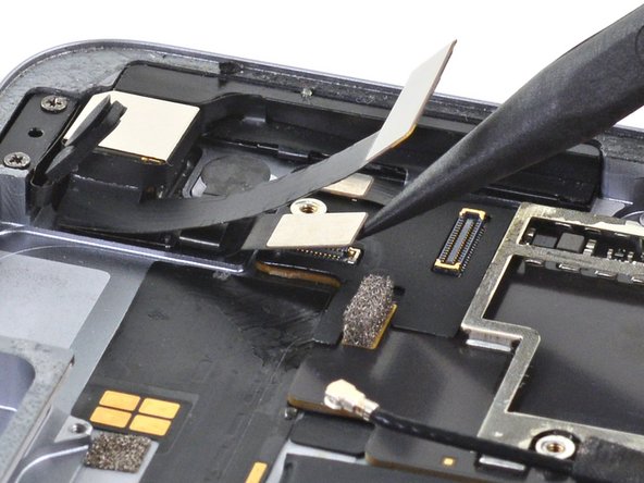
Use the pointed end of a spudger to disconnect the front camera's press connector from its socket.
-
-
-
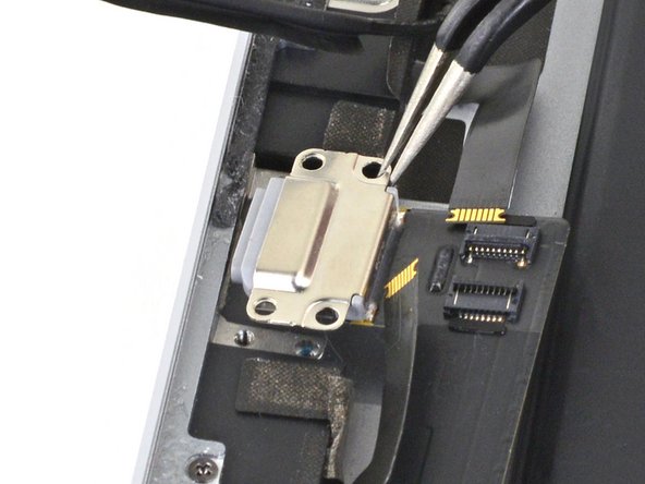
Use a pair of tweezers to grip the bottom coaxial connector on the top interconnect board by its metal frame.
-
Lift straight up to disconnect the coaxial connector from the interconnect board.
-
-
-
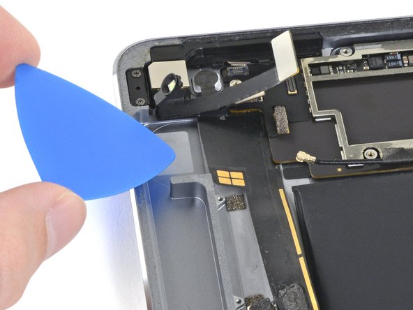
Apply a few drops of high-concentration (90% or higher) isopropyl alcohol to the edges of the top interconnect board.
-
Wait thirty seconds for the isopropyl alcohol to weaken the adhesive under the top interconnect board.
-
-
-
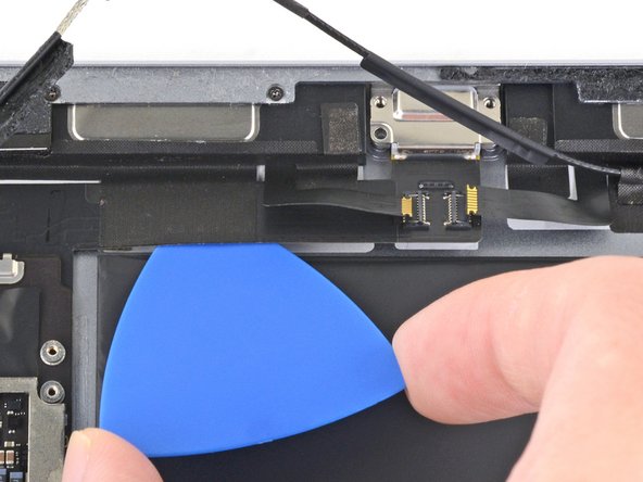
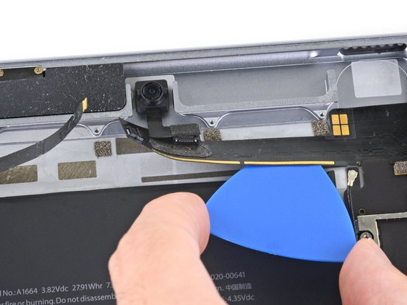
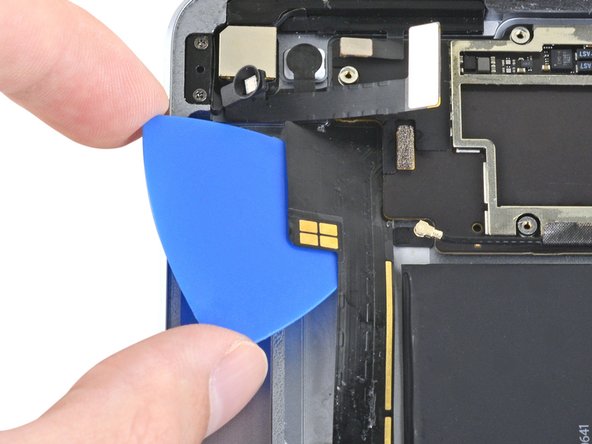
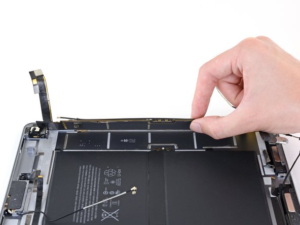
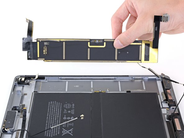
Use an opening pick to cut through the adhesive under the top interconnect board and detach it from the frame.
-
-
-
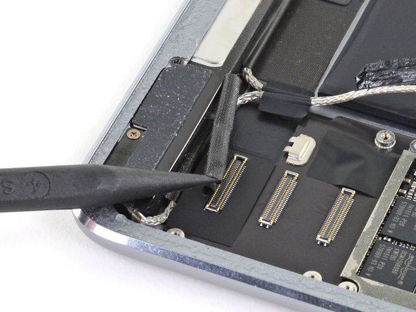
Use the pointed end of a spudger to disconnect the rear camera's press connector from its socket.
-
-
-
Use the pointed end of a spudger to disconnect the power button assembly's press connector from its socket.
-
-
-
Use the pointed end of a spudger to disconnect the volume buttons' press connector from its socket.
-
-
-
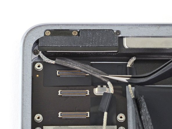
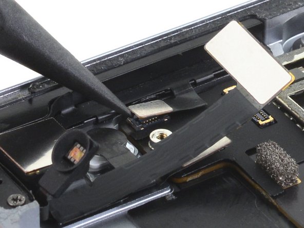
Use a pair of tweezers to remove the sticker covering the ZIF connectors near the Lightning port.
-
-
-
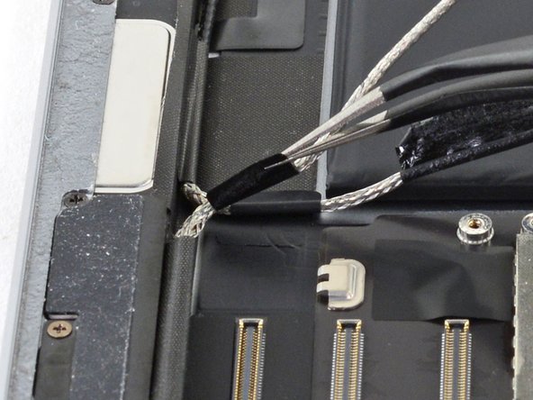
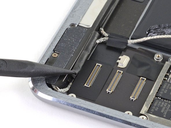
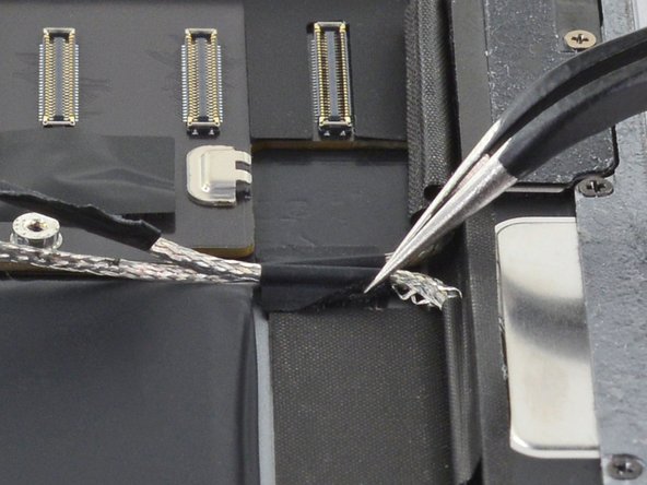
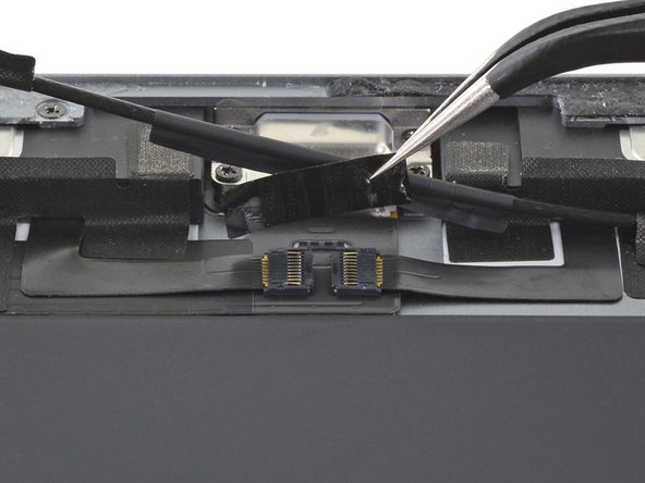
Use an opening pick to cut through the adhesive under the right ribbon cable next to the lower speaker (Lightning port oriented up) and detach it from the frame.
-
-
-
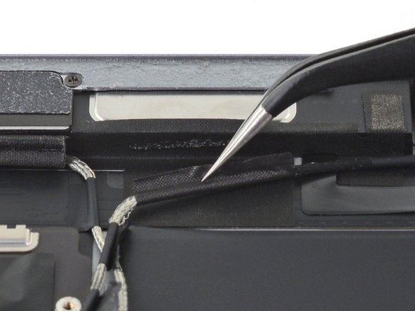
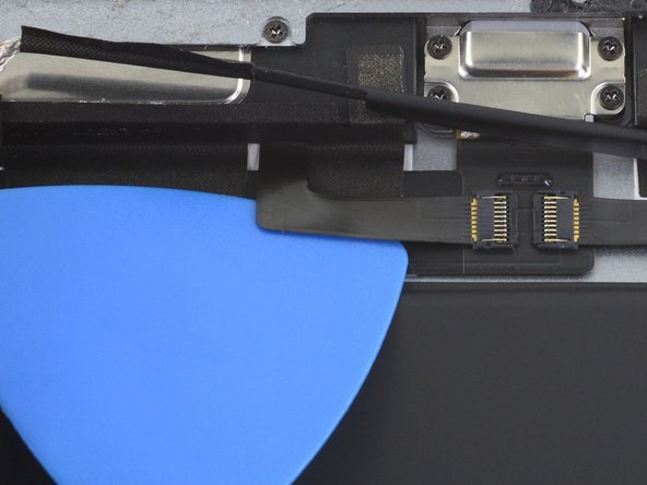
Use an opening pick to cut through the adhesive under the left ribbon cable next to the lower speaker and detach it from the frame.
-
-
-
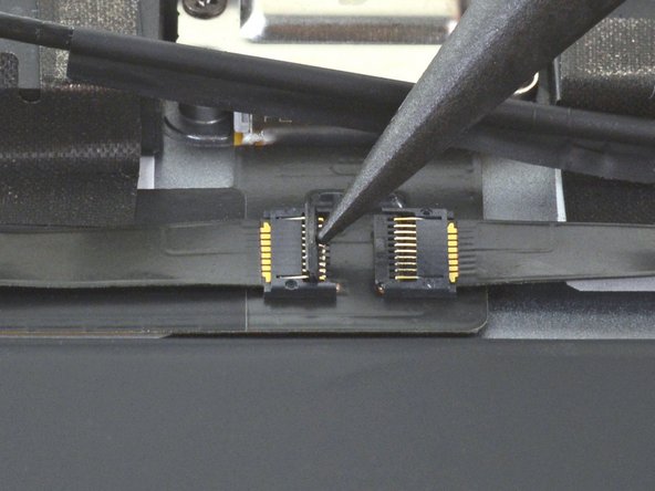
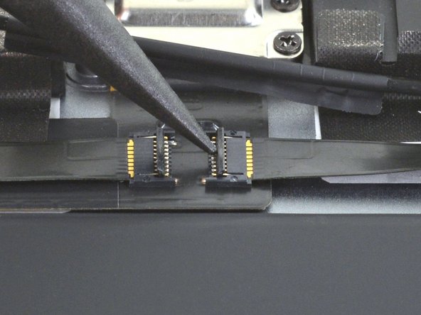
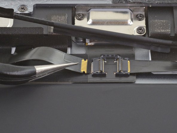
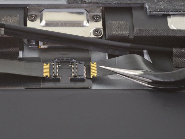
Use the pointed end of a spudger to flip up the hinged locking flap on the left ribbon cable ZIF connector.
-
-
-
Remove the four Phillips screws securing the Lightning port:
-
Two 2.5 mm screws
-
Two 1.5 mm screws
-
-
-
Strips of adhesive secure the logic board to the frame. In the next steps, you'll weaken and cut through the adhesive to detach the logic board from the frame.
-
-
-
Carefully turn the iPad over.
-
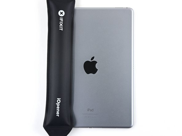
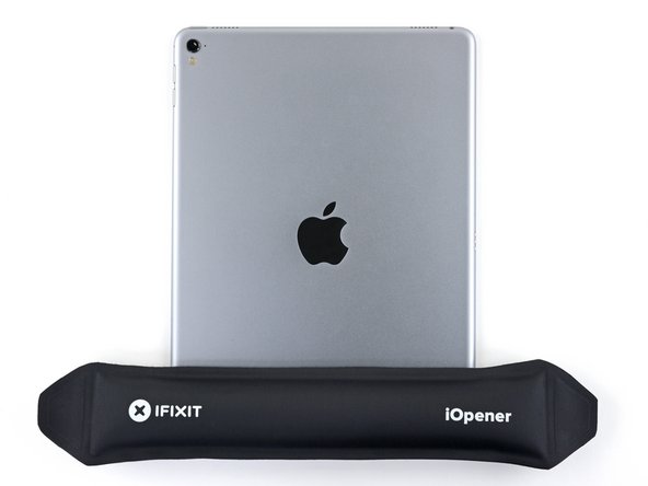
Heat an iOpener and apply it to the top, left, and bottom edges of the rear case for one minute on each edge.
-
-
-
Use an opening pick to cut through the adhesive under the Lightning port ribbon cable to detach it from the frame.
-
-
-
Use a pair of tweezers to lift up the smaller sticker to the left of the Lightning port (when the Lightning port is oriented up).
-
-
-
Use a pair of tweezers to grip the Lightning port by the bottom right screw hole.
-
Pull the Lightning port out of its recess.
-
-
-
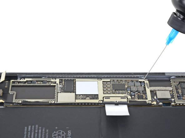
Apply a few drops of high-concentration isopropyl alcohol under the left edge of the upper logic board arm (Lightning port oriented down).
-
Wait thirty seconds for the isopropyl alcohol to weaken the adhesive under the upper logic board arm.
-
-
-
Use an opening pick to cut through the adhesive under the upper logic board arm and detach it from the frame.
-
-
-
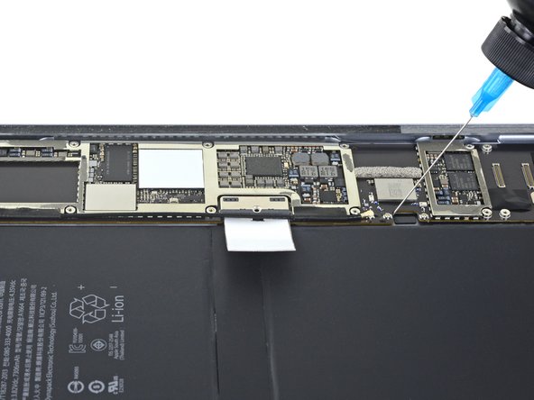
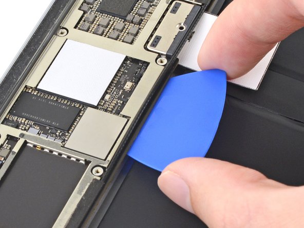
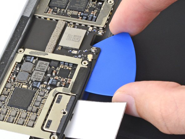
Apply a few drops of high-concentration isopropyl alcohol to the right edge of the logic board.
-
-
-
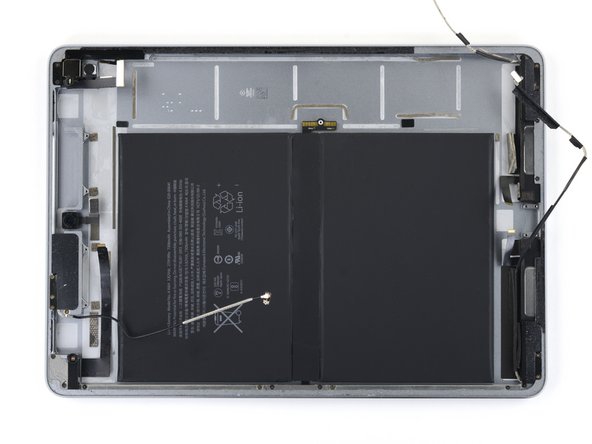
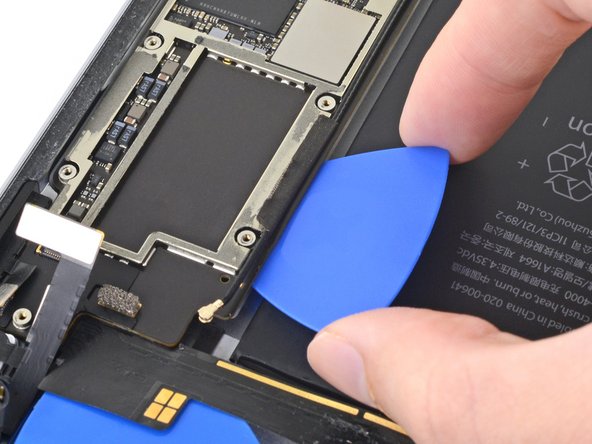
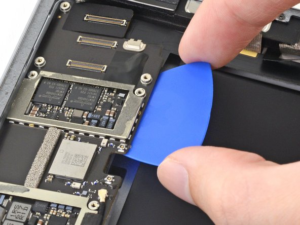
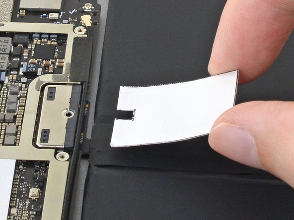
Slide an opening pick about 0.5 inches (13 mm) under the top of the logic board's left side to cut through the adhesive.
-
Remove the opening pick.
-


Compare your new replacement part to the original part—you may need to transfer remaining components or remove adhesive backings from the new part before installing.
To reassemble your device, follow these instructions in reverse order.
Take your e-waste to an R2 or e-Stewards certified recycler.
Repair didn’t go as planned? Try some basic troubleshooting, or ask our iPad Pro 9.7" Answers community for help.
İptal et: Bu kılavuzu tamamlamadım.
4 farklı kişi bu kılavuzu tamamladı.

2 Yorum
where can I buy the logic board for this ?