Giriş
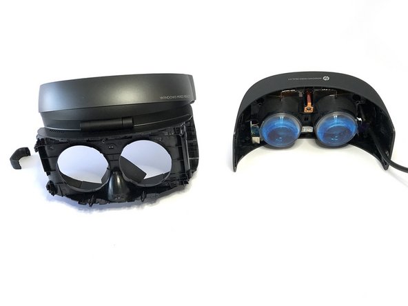
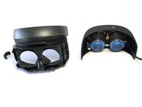
1. adıma gitThis teardown illustrates how to deconstruct the HP MR Headset (DE). This teardown also identifies some of the components within the HMD, and is open to any edits or suggestions for unidentified elements.
Neye ihtiyacın var
Aletler


Daha fazlasını göster…
-
-
HMD Specs:
-
Two high-resolution liquid crystal displays at 1440 x 1440
-
2.89” diagonal display size (x2)
-
Front hinged display
-
Double padded headband and adjustment knob
-
Built-in audio out and microphone support through 3.5mm jack
-
Single 4.00m/0.60m removable cable with HDMI 2.0 (display) and USB 3.0 (data) for connectivity
-
-
-
Remove the foam protector from the velcro-type adhesive strip.
-
Remove the two eye-rings with a flat head screwdriver.
-
Also with a flat head screwdriver, carefully pry apart the outer plastic shell from the HMD
-
-
-
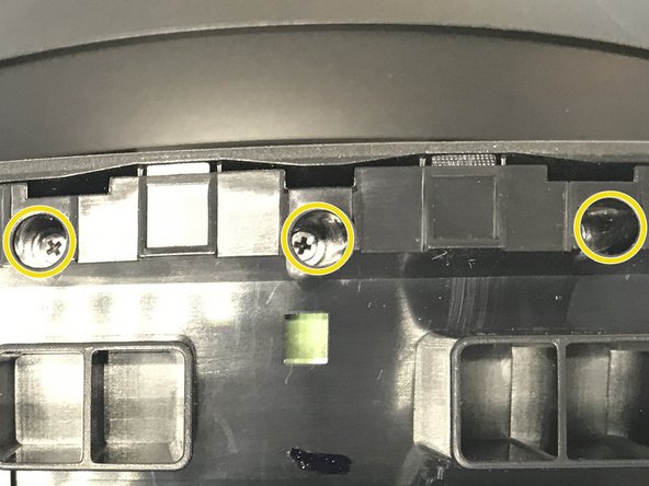
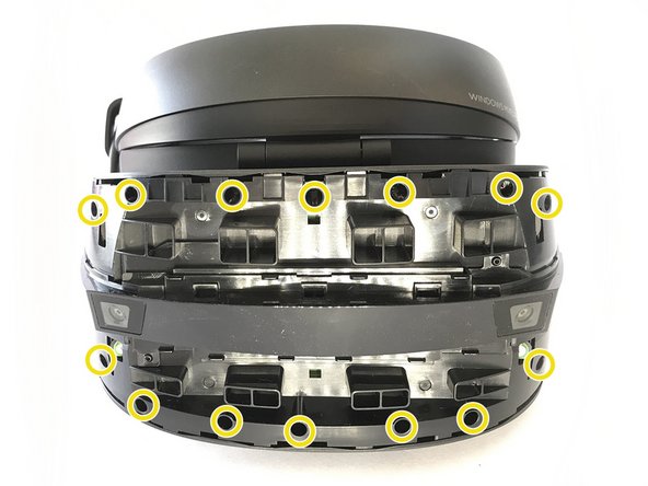
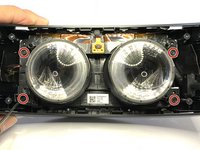
To remove the next layer of protective plastic, you'll need to remove 16 screws
-
1 on each side
-
and 14 on the front
-
-
-
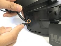
Now that the screws are removed, the next plastic layer can be removed.
-
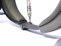
The cable will still be connected to the adjustable head strap. This can be removed easily by prying it off with a flathead screwdriver
-
-
-
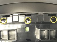
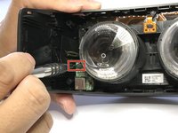
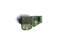
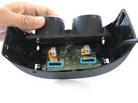
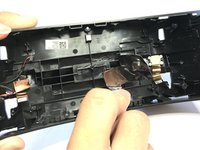
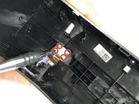
In the bottom left corner of the HMD, you'll find the audio jack and the board attached to it.
-
With a flat head screwdriver, gently pry the connector from the headphone jack board. Once the board has been disconnected, it will fall right out.
-
-
Bu adımda kullanılan alet:Tweezers$4.99
-
Remove four more screws. The bottom left screw will release the audio board support.
-
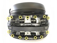
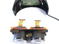
Peel back the lenses at a 45° angle from the bottom up.
-
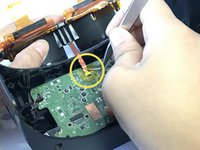
You'll then see two yellow strips held with black protective tape. Peel back the tape with tweezers.
-
Also with tweezers, remove the yellow tape over the connection between the PCB and the lenses.
-
-
-
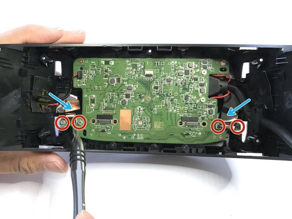
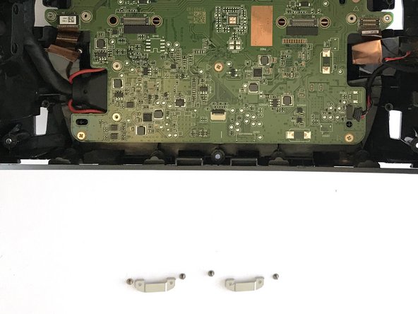
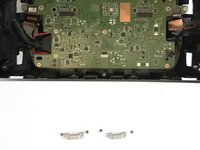
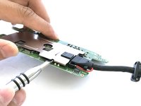
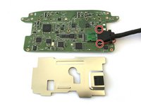
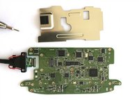
With the lenses removed, you can begin separating the PCB from whats left of the HMD.
-
Remove the four screws to remove the two metal clips on each side of the PCB.
where the LCD taredown also what type of connector for the lcd I must know due both lcd screen are in bad conditon it got fried or something.
-
-
-
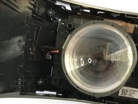
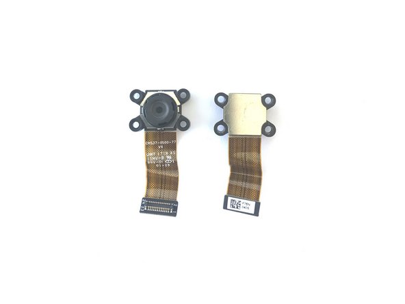
After removed the PCB, you can see the front camera sensor compartment.
-
Remove 4 screws to disassemble the front camera sensor on each side.
-
Cameras were not easily identifiable, however, they looked identical to the cameras we found in our Acer MR HMD teardown. Also had similar part numbers to the the Microsoft Surface 3 rear camera.
-
-
-
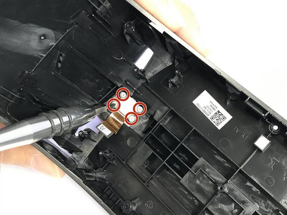
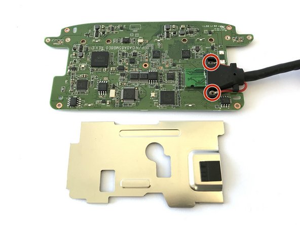
The metal cover to the PCB can be easily pried apart with a flat head screwdriver.
-
After doing this, the two screws connecting the cable to the PCB is revealed.
-
Remove the two screws, then pop off the connector straight up, not at an angle.
-
-
-
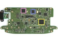
Cypress CYUSB3064-BZXC SuperSpeed USB Bridge Controller
-
Cypress CYUSB3304-68LTXI HX3 USB 3.0 Hub
-
STMicroelectronics medium-density STM32F103C8 performance line microcontroller.
A little disappointed you didn’t spend more time identifying more of the other components like they HDMI to MIPI controller (not a Toshiba component) as well as the as the processor chip used to handle the two cameras that make up the parallax based inside/out positional tracking. But I have not checked out your Acer tear-down, so you might have done that it already.
Actually I done my own tear down and you have incorrectly stated the purpose of the Cypress CYUSB3064-BZXC by just identifying its title. This is actually the MIPI controller for the two LCD panels.
-
-
-
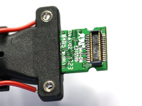
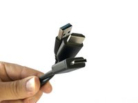
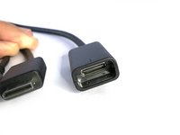
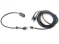
The main cable is a USB and HDMI to a proprietary connector.
-
Instead of plugging directly into the HMD, the proprietary connector plugs into a receptacle which is attached to an embedded connector (shown on the PCB in steps nine and ten).
-
-
-
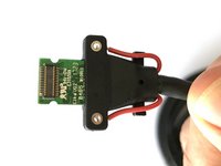
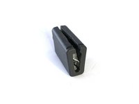
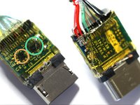
After finding an active cable module within the Acer headset, we were curious as to why the HP headset had no chips on their cable. So we opened up the proprietary connector on the cable (Do not do this. You won't be able to easily put it back together)
-
Under the plastic shell, we found a similar Spectra7 cable module similar to that of the Acer Windows HMD
-
Spectra7 VR8050 USB 3.0 Cable Equalizer
-
Spectra7 HT8181 HDMI 2.0 Cable Equalizer
There are headsets on ebay without the cables. I wonder how difficult it is to splice the connector and remake the male connector board. That doesn’t seem to complicated.
I’m looking same route did you find the pin out? is just cables….
Thank you
I bought one of the 49$ headsets. Like you said “cables is cables". My backup plan if splicing doesn't work out (it should nt be too horrible using breakouts ) is to rip it apart and find the usb c pinouts inside and run a cable directly from that to pc , then just a mini displayport to hdmi should be fine in the normal jack. Thoughts? One thing, I cant put in the usb c or hdmi signal conditioners, so I'll have to keep the cable short, less than 3 meters according to this. https://www.digikey.com/en/articles/usin...
Is there any kind of “signal conditioner" or booster that can be plugged in later?
-


19 Yorum
This is fantastic thank you! Any plans on tearing down the other four MR headsets from Microsoft?
Hi there,
I am wondering if anyone knows the components I have highlighted.
[IMG]http://i63.tinypic.com/2hxsz1f.jpg[/IMG]
[IMG]http://i66.tinypic.com/2mm5zyu.jpg[/IMG]
[IMG]http://i63.tinypic.com/33w8hop.jpg[/IMG]
My HP WMR unit had a power surge and has burnt out most of these components.
A good electrical engineer friend of mine has cast a close eye over all the other components on the board, showing no physical damage (which I know doesn’t mean that they all ok).
I live in hope that I will be able to repair my WMR headset, as I have myself had plenty of experience with SM components.
Just identifying the values of these components is proving to be mighty tricky!
I believe (A) 6 pin “EDVGA” are voltage regulators - SOT23-6?
(B) Transistor? - “NA ID9” ?
Appreciate any help :)
Paul
Any info on the sensor in the center mounted between the lenses?
From what i’ve seen on other headsets it’s a light sensor ..
controls brightness during light bleed.
Hi. My cameras stopped working, and I think it's because of the USB cable damage.
Do usb3. 0 sstx ssrx lines conduct current when there's no power on hdmi & USB equalizers? I'm sticking one probe of the multimeter to the USB's sstx and the other one to every pin of the combined HDMI-USB plug.
USB 2.0's lines conduct current just fine, but usb 3's line are quiet.
Thanks.
Can you finish this tear down by removing the screens completely.?
There’s 4 hidden screws above the light sensor under some black tape, peel it off to reveal them…if i’d’ve known i wouldn’t have deconstructed the whole hand-band. Once unscrewed you got to tilt the hinge back and forth to unclip it from the visor
The “EDGVA” devices appear to be boost converters/drivers for LED backlights, one for each LCD.
The “NA” parts are probably N-channel MOSFETs for dimming the displays (G/D/S = gate/drain/source) .
Is there any way to just remove the headstrap from the main part of the unit? I’ve managed to remove some caps on the hinges but it didn’t reveal any screws underneath unfortunately.
look at my reply to @Wilddog73 comment
you have the HDMI cable as spare for the samsung oddysey + I just need the cable
please
Can I use 2 cables one the HP HDMI with one flat end and a USB ? I guess the USB I can tear down one end and solder the wires, any one with the pin out?
Thank You
This combo cable is the weakest link. That explains why you can buy a headset (without anything else) for 22 S from ebay( I got one as a backup). As the good iFix showing if you open the Oculink male end, you will realize it is practically repairable.
Here is the trick:
Buy the short cable from HP. HP PART NO: L04717-001
Comes around 41 CAD (38+ TAX =FS). I believe it's a plain cable without chips, that's exactly what we want.
Buy two active USB 3 and HDMI 2.0 extension cables from Amazon 10 CAD each. You have to be careful with USB 3 extension cable- which deliver the 0.9 A power to the headset display. Not all USB 3 works.
I'll give you mine,which is working,
Search Amazo:
10 feet HDMI 2 extension- HAGIBISTECH
10 feet USB 3 active extension- Cable Matters
Each is 10 CAD. Buy 2 USB 3 as it may have a chip making it more susceptible to failure. If it does, use the other. Good Luck
Oops %#*@ typo :) , I mean to say the the cable is hardly repairable . And good luck with finding those 2 cable equalizer chips. So the trick is buying the cheap short plain vanilla cable with the Oculink end from HP and export the able equalizer chips to the extender cables, which can be replace in ta possible future failure ( 10 CAD each).
Question Does any know how to where do I get a replacement part for LCD screen for my headset i got 2 bad ones one is turned gray color and the other is mess up I very curious.
I have a Lenovo Explorer that sometimes has loud static or no bass, sometimes has USB error 1-4 and 14-1, and sometimes gets hot. I measured 12K ohms to ground on multiple capacitors on the back of the PCB behind the “Cypress CYUSB3304-68LTXI HX3 USB 3.0 Hub”. Most other parts I measured were 18-22K ohms to ground. I don’t know what values to expect and don’t really know what I’m doing. I have no spare known good cable to test against, for all I know it could be the cable. The same issue happens on 3 computers.
I measured less than 10 ohms resistance between the USB negative data pin and an HDMI data pin. Probably a short in the cable causing this. A friend rolled on the cable with a swivel chair months before, maybe it just took a while for the damage to the wire insulation to get worse.
Vincent -